by bwireless | Apr 2, 2021 | 5G, Augmented Reality, Internet of Things (IoT), Wireless
The combination of the three (independent) technology areas edge computing, private/dedicated 5G networks and IoT could be the hottest cake you find in the telco/IoT industries right now. These three concepts are not simple for everyone to digest. If you’ve worked with 5G for the past ten years you probably haven’t spent too much time learning about cloud computing, microservices, containers and enterprise IT architectures. If you are an IT network consultant, the node named “UPF” in a 5G core probably sounds like a packet delivery supply chain company. A lot of people also believe that private 4G/5G networks are not suitable, useful or cost-effective for enterprises to install and use.
In this article, I will explain what these three tech areas are made of and how they overlap. I also describe my own lab setup which you could copy and get your own, private 4G (soon 5G) mobile network and IoT platform running on an edge cluster.
Let’s start off by taking a look at the three technology areas and describe what they do and why they are important.
Internet of Things (IoT)
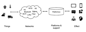
There is no one definition of what IoT actually is. In the book Things you should know about the Internet of Things, I stick to the “definition” shown in the figure below which holds for pretty much any IoT solution. It describes that IoT consists of the following four layers:
- A Thing is a device that has a network interface and can uniquely identified within a network.
- Networks can be of any kind. The standards shown in the figure below are just examples. This article focuses on private/dedicated 4G/5G networks, which provide quite unique features related to Quality of Service and mobility. We get back to this further down.
- The Platform layer is responsible for managing Things, receiving and converting data, storing data in various ways, creating rule chains to trigger events and alarms, visualise data and provide Application Programming Interface (API) to other systems. If you’re interested in learning more about IoT platforms, this is an intro article. There’s a lot more information in the book I referred to above.
- What we ultimately want to achieve with an IoT solution is to create an Effect. This could range from visualising water levels to feeding a machine learning algorithm. The desired effect has to be measurable and fully understood before an IoT solution is designed.
A term that often pops up when working with industrial IoT is Industry 4.0. The reason is that a lot of robots, cobots, machine learning models, condition-based monitoring, digital twins, asset/people tracking and other stuff that Industry 4.0 is about need a lot of data from many devices and sensors to function properly. Reliable IoT is a requirement for all these technology areas to take off in industries, production environments, hospitals, smart cities and enterprises in the years to come.
Private/dedicated 4G/5G networks
As mentioned above, machine learning algorithms and many other consumers of data demand not only IoT data, but good IoT data showing up at the right time without any packet loss. This requires sensors of decent quality, but also wireless networks that can deliver deterministic coverage, mobility, security and quality of service in a way not offered by technologies in unlicensed 2.4 GHz or 5-6 GHz frequency bands.
A very clear trend in many business verticals is therefore to consider deploying an own, local mobile (4G or 5G) network to connect CCTV cameras, trucks, forklifts, digital signage screens, drones at construction sites, combined indoor/outdoor asset tracking systems, Augmented Reality glasses and other services and gadgets.
From an architectural perspective, Wi-Fi is different from a mobile network as it doesn’t come with a core network, and for many years there has been zero chance for an enterprise to install, configure and manage their own 4G/5G infrastructure. If you talk to an IT organisation, they even refer to Wi-Fi as “wireless” as it has always been the only relevant choice when unwiring a Local Area Network. 4G and 5G have been seen as primarily outdoor mobile network services provided by Mobile Network Operators (MNOs).
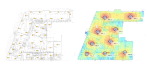
Within just a couple of years, this has changed completely. A private 4G or 5G network can now be deployed by an enterprise with the same ease as a Wi-Fi system. The price point has gone down and is on par with and sometimes lower than Wi-Fi. One major reason is that the coverage you get from a 4G/5G small cell is 5-10 better than what a Wi-Fi AP offers. The figure below shows a Wi-Fi design next to a 4G small cell design in the same building. Note that the output power per radio node in the 4G network is typically lower than the output power configured for the Wi-Fi APs. The improved 4G/5G coverage comes from better chipsets and how the radio protocol is standardised. The reduced node count can be translated into a lot less hardware, SW licenses, cabling and PoE switch ports needed.
The new 4G/5G networks are simple to manage even for an organisation not familiar with how to plan, design or operate a mobile network. Integration to existing IT services and reuse of existing functions like DHCP, client certificates and segmentation of traffic looks just like the IT technicians are used to. Even the management systems have the same look and feel and provide toolboxes for API integration towards existing management/ERP systems.
The quick adaptation of 4G/5G to enterprises has been enabled by some important factors. IoT is of course one. Here are three others:
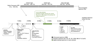
1. Access to spectrum/frequencies for non-MNOs to run private 4G/5G networks on. The figure below shows some of the most common Radio Frequency spectrum bands which either are licensed (often to MNOs), unlicensed (for everyone to use) or lightly licensed (free or very cheap to use for anyone). The Citizens Broadband Spectrum Service (CBRS) in the US is one such lightly licensed spectrum model. Similar models exist in Germany, the Netherlands and the UK with many more European countries to follow in the coming years. This said, many MNOs are also using their own spectrum to build private networks.
2. Open source communities and movements. What will fuel the private 5G market even further is the fact that open source software exists for pretty much anything today. Regardless if you want to develop an IoT platform or a 5G core network, you can find and grab already existing software components or entire projects from Github and get started. With a cloud-native approach, services can be disaggregated and end up as loosely connected microservices and often scale from a Raspberry Pi up to entire datacenters. Open RAN (O-RAN) is another type of (related) movement which aims to break the traditional vendor silos in cellular networks and disaggregate layers in order to open up for different vendors to be used in the same solution.
3. Cloud-native computing. 4G core networks (explained below) used to be extremely complex, costly and bulky. An MNO typically has one per country and in some cases one serving the radio networks in several countries. Nowadays it is possible to build these core networks on virtual machines or even on microservice architectures in container environments. This allows for an entire network to be scaled down and run on a single off the shelf server. Services are interconnected via API. If we need more resources of some type (signaling, mobility, user plane etc.), new containers of the right type can be started in milliseconds and connect with existing services via API.
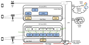
The cloud-native evolution is further explained in the figure below where we’re looking at an enterprise network with three different wireless networks. The first one is a traditional Wi-Fi AP being connected to a WLAN Controller (or just to a switch). Authentication options are left out in this example.
The second network is a 4G one. Compared to Wi-Fi, we need to add an Evolved Packet Core (EPC) network which roughly consists of:
- A control plane responsible for authentication, authorization, policy control/enforcement and seamless mobility.
- A user plane taking care of the IP packets being transmitted. This is more or less routing of packets going to/from the mobile devices. A Netflix session, the content of a website, emails etc.
The third network introduces the 5G core which contains pretty much the same functionality as the 4G core, but everything is renamed as “Functions” (think: microservices). “AMF” is for example the Access and Mobility Function. So the blue marked boxes in the 4G core and the blue boxes in the 5G core are covering the same functionality. The same goes for the orange boxes. The ones with green text represent new 5G core features adding structured/unstructured database storage, network exposure (API), service discovery and message bus and something called Networks Slicing. All of those (except the slicing) are features you find in cloud-native computing and container environments. The question is: Who benefits the most from 5G being extremely flexible and scalable to deploy? Well, private/dedicated 5G networks is a good bet, especially when running it at edge locations.
All of these transition factors play important roles in the rapidly approaching future where private 5G networks will be deployed in scale for industries, hospitals, enterprises and universities and sit next to existing Wi-Fi networks. Do we need both? Definitely:
- The bandwidth demand is there and will only grow with more video and AR applications.
- Voice and video services of different types (native dialling, Teams, Whatsapp, Facetime, Webe, Hangouts, VR calls or other personal favorites app) will become more important in the post-pandemic world.
- There are many use cases Wi-Fi simply isn’t suitable for that 5G will handle with ease. Think of anything that has to perform in a congested area, something that moves, something that has to deliver data deterministically, something located in areas where you can’t mount radio nodes every 30-50 meter or something requiring a high level of security.
- Mobile network indoor coverage is poor in many countries. A private/dedicated network could be used to facilitate Neutral Host Networks (NHN) and allow for new types of RAN sharing models. The UK is forerunners in this area with the Joint Operators Technical Specifications (JOTS) which allows for 3rd party players and NHN providers to build indoor networks that the MNOs can utilize via agreements.
The Edge environment
A simple way of explaining where we find the Edge would be to say it sits between the cloud and end devices or services. The purpose is generally to distribute compute, storage and database functions closer to the device to cut costs, lower latency or provide local survivability of services.
One example could be a climate system and a surveillance camera (the “devices”) mounted in a bus. Let’s say they are connected to a public cloud service (the “cloud”) via a mobile network. An Edge node could in this case be a vehicle-mounted server responsible for collecting, analysing and acting on local data before it’s sent to the cloud.
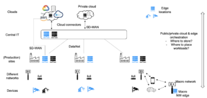
Where and what the Edge is really depends on who you are and what you offer. If you’re a Mobile Operator, you might see your Edge as the edge of your mobile network which consists of radio base stations (the “devices”) and a mobile core network (the “cloud”). This is illustrated with the “UP termination” boxes in the figure below. The purpose of distributing the UP in this case is often to cut latency for specific applications. The “device” could also be any terminal provisioned with a SIM card or eSIM.
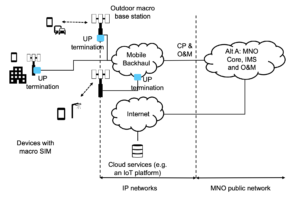
If you’re an enterprise, an energy company, a system integrator or a production company, your Edge is often a local data center or something even closer to your end devices (see examples in the figure below). The cloud is normally a private or public cloud reached via a WAN or SD-WAN connection.
For these types of organisations, “low latency” could be a reason to install a local 5G network, but these factors are more common drivers:
- Local survivability. If someone cuts the WAN to the site or if there’s a power outage in the area, the locally deployed mobile network will still deliver.
- Simpler segmentation. If the traffic leaves the site and comes back again via the company firewall, segmentation could become a hassle. Especially if the number of devices grows and you run out of IP addresses in a defined scope. If the local 5G network terminates the traffic on premise on an Edge node, things will look just like in a Wi-Fi network, and you can use private address ranges with a large scope.
- High security and trust. Most enterprises want their traffic and certificate handling to stay inside the enterprise network.
- Cost control.
- No dependencies and high flexibility. Owning and managing your own network means you can also scale it when you need. If there is more traffic or more users, you can handle the situation by adding more radio nodes.
- Run the 5G networks on non-macro spectrum (either lightly licensed or a licensed chunk which is not used by the macro network in the area). Doing so means you don’t have to plan out your radio network with respect to the macro network energy. This leads to a much more lean and simple design, and the range per radio node is greater without competing noise and interference.
Building your own enterprise edge + 5G + IoT solution
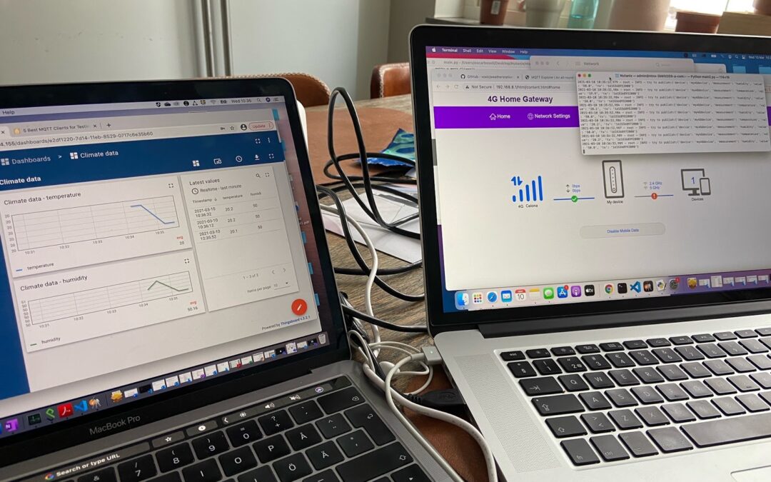
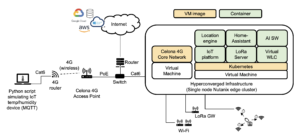
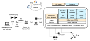
Alright, now when we know what private 5G, IoT and edge computing are about and how they are used together, let’s get our hands dirty and combine these technology areas in practice. Building an own lab and testing things is often the best way to learn how stuff actually work. The setup I will demo looks like in the figure below and is based on the following components:
- Intel NUC with 64GB RAM, a Xeon processor with 8 cores and 3x1TB of SSD storage. Although this is a single node, it will from a Hyperconverged Infrastructure perspective be seen as a single node “cluster”.
- Nutanix Community Edition which provides a hypervisor (AHV), operating system (AOS), virtualization of the infrastructure (storage, processor, network interfaces), Kubernetes and a management plane for FCAPS (Fault/Configuration/Alarm/Perfomance/Security/Software management).
- On the Nutanix cluster, we spin up two Virtual Machines running:
- A 4G mobile core network from Celona (yes, I said I will build a “5G network” to catch eyeballs, but from a demo point of view 4G and 5G are indistinguishable, and I can easily upgrade the setup to 5G Stand Alone once the SW and NR radios are around later this year). This core network is created and adapted for IT organisations and all configuration that has to be done is related to IP addresses, DHCP relay, VLANs, Quality of Service etc. Just like in a Wi-Fi network. Installation of the image file on the VM is a quick and very straightforward process.
- Nutanix Karbon Platform Services (Kubernetes cluster) where we will run the IoT platform and related services.
- 4G base station (also referred to as an Access Point) from Celona.
- Laptop where we simulate various sensors with Python scripts. “Hey, why don’t you use a 4G sensor for this?”. Well, I don’t have one with 4G connectivity at home, so I do it like this instead.
- A Huawei router used to connect the laptop to the Celona 4G network.
I leave the IP configuration out here and move directly to the setup. The following steps were carried out when setting up this environment:
1. Install Nutanix CE on the NUC to bring up the edge cluster. Several guides on how to do this are available. Here is one: https://getninjad.com/2018/12/29/nutanix-home-lab
2. Once the Nutanix platform is up and running, set up the VM for KPS. This will provide:
- A Kubernetes cluster where you can run containers (one of them will be your Thingsboard open source visualization platform, see below).
- A service domain where you can configure ingress of data from the IoT device, a queue for incoming packets, conversion of the data to desired formats and the API calls for pushing the data to the IoT platform.
Luckily, my friend Emil Nilsson at Nutanix has written an excellent guide on how to do all of this. If you run it through you’ll set up an MQTT broker, ingest control for data packets, a Kafka queue, a consumer group fetching packets from this queue and the IoT platform (Thingsboard) which is populated with data via their API. You find the guide here: https://github.com/voxic/Thingsboard_on_KPS
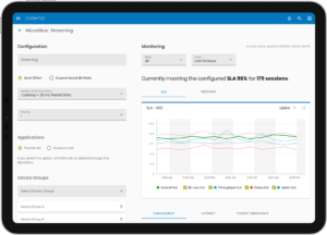
3. Setting up your 4G network is a very straightforward process where you start off installing your Celona core network on a VM in your Nutanix cluster and then log in to the Celona Service Orchestrator where all configuration of IP addresses, DHCP, sites and SIM provisioning is done (see figure below for example view). Important here is that you don’t need to know anything about the underlying 5G core network services described above. It’s all delivered as a service and the installation is done in no time.
4. If you need a Python script to emulate the sensor on the laptop, Emil is your friend again. Here’s a link to one of his other Github projects with sample code you could use as the base: https://github.com/voxic/weatherstation-simulation
The management tool for both the Nutanix environment and the Celona network are developed for IT organisations with an API-first mindset and if you have configured Wi-Fi networks before you will recognise almost everything on the radio/IP side. The main differences in configuration are related to ability to define quality of service per application/device and actually trust that your radio network delivers under load.
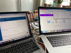
The result of this setup is an IoT device communicating over a private enterprise 4G network, feeding the open source IoT platform with sensor data which is displayed in widgets. The result of the test setup is shown in the figure below where we see the Thingsboard dashboard to the left and the script emulating the sensors on the screen to the right.
What’s next?
Now when our test environment is up and running, we could relax and just watch our sensor data flow through the 4G network via our edge cluster to the IoT platform dashboard. When we have done that for ten seconds, we can move on using our cluster and add the next wave of projects. This is what I’m aiming for:
- Get more devices supporting the configured 4G band. I’m looking at a couple of video cameras. The ultimate goal is to test a Celona feature called Microslicing which allows you to configure individual quality of service classes per application/device. You find a really good demo on how this is setup in order to give different priority for different services over here: https://www.youtube.com/watch?v=UD7sS7P3wGo
- Add an Artificial Intelligence application to your Kubernetes cluster. In my case, I will feed an image recognition application with one of the camera streams. The application identifies if someone or something is moving outside my home during nighttime, and if the object is a human I will save the video and send an event to my home automation system which is based on https://www.home-assistant.io (this also runs on KPS in my Nutanix cluster).
- Add more applications to the cluster. Apart from the AI application and the Home-Assistant automation platform, I’m also planning to add an open source LoRa Network Server (Chirpstack), a location engine for asset tracking and a virtual WLAN controller (Ubiquiti). This will result in the configuration shown in the figure below.
- Send your IoT data to public cloud services. Nutanix provides cloud connectors to AWS, Microsoft Azure and Google Cloud. The setup is easily done by setting up a new consumer group in the KPS data pipeline and forward incoming packets to one of the Hyperscaler clouds as well.
- Upgrade the 4G network to 5G. This will happen during the summer/autumn 2021.
In the end, what your managed edge cluster will look like is really a question of use cases and desired application support. Build – play – have fun!
I hope you enjoyed this article. Please feel free to reach out if you have any questions regarding the setup or any of the technology areas discussed.
by bwireless | Nov 2, 2020 | Asset tracking, Platforms, Wireless
This is a sample chapter taken from the book “Things you should know about the Internet of Things” which was released by bwireless in 2020. Pictures, reviews and more information about the book can be found here.
9. Tracking and wayfinding
On the surface, knowing the exact position/location of a device or sensor is only important if you are trying to find that object. However, looking deeper, if you automatically know the position of a device installed in the field you can simplify inventory, support and troubleshooting. This can prove to be invaluable for the Total Cost of Ownership (TCO) of your IoT business model.
As an example, consider an activity-based office solution where sensors are placed under tables and in conference rooms to detect the presence of people. When installing these devices, they are tied to a position on a map, and this process is manual if the devices cannot be automatically located by the network. Will the office space be refurnished during the contract period? Will batteries have to be replaced on some of the devices? Will the company reorganize and move people between floors or buildings? If the answer is yes to any of these questions, the provider of the activity-based office solution would end up with a much better service model if they did not have to visit the office and hunt down all devices from time to time. Similar benefits are obtained when streetlights, parking sensors, water meters, industrial robots and other things report their position automatically.
When tracking items or people, the network layer in the IoT stack often melds together with the device/sensor layer. The network acts as a sensor when hunting for devices. For this reason, IoT solutions built to position objects or humans come with very specific requirements on which network protocols to use.
In this chapter we look at:
● An overview of what we mean by tracking and wayfinding.
● The components and methods used by positioning systems.
● Common technologies used by indoor and outdoor wayfinding and tracking systems.
9.1 Tracking and wayfinding overview
Although the human brain is highly intelligent and comes with a good visual memory, most people spend time every day looking for lost things or simply trying to find their way around. We commonly use Google maps or custom apps in areas like malls or stadiums, and these tools are relying on various radio protocols to position people and objects.
9.1.1 Terminology
It is important to first make some distinctions in terminology.
● Positioning
Positioning refers to determining the location of an object indoors or outdoors. If the object to position is ourselves, we often rely on maps, signs or a GPS based app. When positioning objects, GPS, cameras, QR codes or wireless networks are commonly used.
● Wayfinding and blue dots
Wayfinding is how we find the way from A to B. A simple example is when we look at digital or analogue signs or when we type in an address in Google Maps and get instructions on how to get to the destination.
If we look at Google Maps in our phones, we see a blue dot showing where we are. This is the position calculated by the device. It is also possible to generate blue dot maps indoors, and they typically come with location-specific apps for wayfinding in areas such as offices and hospitals. Google has also added blue dot support in many public areas including airports and malls.
● Tracking
While wayfinding aims to provide information about where we are and where we are going, a tracking solution helps finding pets, children, goods, wheelchairs, cars and other objects and living creatures in various environments. Tracking can also be used when analyzing behaviors, or to build knowledge about how to plan out, for example, an airport or a shopping street in a city.
● Proximity
Proximity simply means being close to something. In many cases, knowing if you are close to an object is precisely the information we need – this is what solutions like Apple’s iBeacons or Tile are used for. If a customer is close to a product in a store, we can send a notification about an offer via an app. If we are looking for car keys, it is often enough to know whether they are in the car or if we left them inside of the house. We cover both tracking and wayfinding solutions in this chapter.
9.1.2 Which resolution is required when positioning an object?
As for most IoT solutions, it is important to spend time understanding what kind of precision is required to achieve a desired tracking effect. If we want to know where a missing child is located in a forest, 50 meters tracking resolution is probably good enough. If the same child gets lost during a big outdoor concert, +/- 50 meters is quite a lot and we might need something more detailed. If we are looking for a specific pallet with goods in a warehouse, we could get away with a proximity solution telling which part of the building these kinds of pallets are located, but it could also be relevant to get down to sub-meter resolution. A doctor looking for medical instruments in an emergency room may require centimetre precision and 3D resolution. It all depends on the use case. The defined resolution of the tracking sets the scene for what the technical solution has to look like.
Higher than required resolution drives unnecessary cost while insufficient resolution misses the target and makes the tracking solution useless.
9.1.3 Wayfinding today and tomorrow
Most wayfinding solutions today are based on some form of well-known radio technology such as GPS, Wi-Fi or Bluetooth. However, some other options are on the rise:
● Phone based Augmented Reality apps can use the camera and image recognition to provide excellent tracking resolution while at the same time adding a marketing layer of information in the picture. Consider a grocery store where you first get an exact route to the pasta and once you are there an inspirational video pops up showing a delicious dish.
● Cameras are quickly evolving and are today already used in many indoor tracking solutions. Cameras for counting people or undertaking pattern recognition could be placed in the ceiling and give exact information about how people move around a store or in a building. This solution has been implemented in airports and offices with great results. A surveillance camera system in a hospital could not only tell where beds and wheelchairs are located but also give additional useful information such as bed occupancy, or identification of faulty equipment such as a broken wheelchair. A surveillance camera system in a parking lot could be used to detect which paths cars are taking in the area.
● While most wayfinding applications today are visual, user interfaces based on audio are also emerging. This is not only useful for visually impaired people, but it also removes the need to install apps and to have a network connection on your device. An audio-based interface would use a wayfinding solution and present directions via sound rather than visually.
9.2 Wayfinding and tracking components
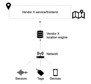
Most tracking solutions mimic our four-layer IoT stack and consist of the following components shown in the figure below.
● Things: Tags, sensors and devices
A tag is configured to send out a message containing the device ID and potentially telemetry data like temperature values, accelerator information or battery charging status, at regular time intervals. Commonly in Wi-Fi networks, the tags do not always connect to the network, they might just broadcast their ID and additional information and then it is up to the network to capture the information. This is often referred to as an “RFID tag” by the Wi-Fi community, which should not be confused with the passive RFID tags described later in this chapter. Any IoT device coming with a wireless chipset could in theory also be tracked by the wireless infrastructure.The actual resolution depends on how the wireless network is built and which features it comes with.
● Network
An asset tracking network can either be an existing grid of base stations or access points based on 4G, Wi-Fi or other existing nodes. It could also be a purpose-built tracking network. In those cases, the network nodes are often referred to as “base stations”, “observers”, “locators” or something else, and they come with their own management system.
● Location engine
This is our platform layer where the actual location of objects is calculated and where network nodes could be managed.
● Application layer
For tracking and wayfinding solutions, graphical user interfaces are of course common in the application layer, but depending on what is positioned it could also be a fleet management system, an inventory system or, as mentioned above, an audio-based interface.
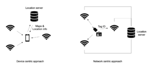
9.2.1 Network centric and device centric tracking methods
A Radio Frequency (RF) based tracking solution can be network centric or device centric. In a network centric approach, the device (or tag) sends out a data packet that the network uses when triangulating the position of the device. This is commonly used for asset tracking solutions where devices can be simpler and need to survive for years on a small battery. In a device centric solution, the device instead listens to the network and tries to figure out where it is based on what it can hear. This is how a GPS receiver and most phone-based wayfinding systems work.
9.2.2 Radio frequency positioning methods
Once we have a network in place, we can use different methods to figure out where our devices or tags are located. The figure below shows the difference between the most common alternatives. All five methods are described below.
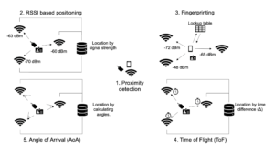
1. Proximity (presence detection)
In many IoT use cases we are only interested in simply knowing if an object is in a defined area or not. In this instance a proximity-based solution could be what we are looking for. Scanning of instruments in hospitals, location-based advertisement in stores and passage systems are often based on proximity with short-range RF protocols.
2. Received Signal Strength Indicator (RSSI) based positioning
Network nodes like access points, observers or locators are listening for incoming packets sent from devices and tags, and for each packet the signal strength is recorded by all nodes. This information is sent to the location engine which uses the information when triangulating the position of the object.
The challenge with RSSI based positioning is that the signal strength is reduced with the square of the distance from an object, and the quality is degraded by reflections and attenuated when traversing through various materials. Any time we double the distance between the tracked object and a network node, the signal level drops by at least 75%. This means that RSSI positioning is often unreliable unless the network nodes (for example Wi-Fi access points) are placed closely together. In environments where reflective metal objects are present, the calculated position can often jump around both horizontally and vertically and result in “floor-hopping” which means a positioned object could end up on the wrong floor in the user interface. Common resolution in RSSI based Wi-Fi and Bluetooth positioning systems is often 3-10 meters if we design these networks properly, but if there is a lot of metal or open atriums the precision could quickly be degraded.
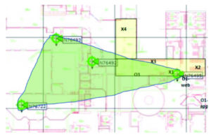
A good rule of thumb is to place the base stations (or access points) fairly close to each other (8-10 meters for Wi-Fi, 5-10 meters for Bluetooth) and use the “rubber band principle” shown in the figure below when designing the network. If we place an imaginary rubber band around the network nodes, the green-shaded area covered by the band is where we will have decent resolution in our tracking. This means we typically want to push the APs further out to the corners of the building, unlike traditional Wi-Fi access networks where APs are more centralized.
3. Fingerprinting
If we want to increase the precision and reliability of an RSSI based solution, we can consider using a method called fingerprinting. The idea is to perform walk tests in the tracking area, stopping every few meters to measure what the radio environment looks like and then store this into a fingerprint database. Later on, when a device wants to find its location, it scans the radio environment and uses the result to query the database which can be located either in the device, in the location engine or in a backend service.
Fingerprinting could increase accuracy of a tracking solution by up to several meters and help avoid floor-hopping, but it also requires new walk tests from time to time to ensure the lookup-table is accurate. In Wi-Fi environments, solutions from Aeroscout/Ekahau make use of fingerprinting for both healthcare and industrial applications. Google uses a similar technology when providing indoor wayfinding support in Google Maps.
4. Angle of Arrival (AoA)
In indoor locations that are open and come with ceiling heights of 5-6 meters or more, it could be worth considering an Angle of Arrival (AoA) positioning method rather than one based on RSSI. In an AoA network, the access points are equipped with antenna arrays that can measure the time difference of incoming signals and filter out copies generated by multipath propagation. The result is that the accuracy of the positioning can be improved to below one meter. AoA positioning is not dependent on the signal strength of an incoming packet, it only looks at the delta between bouncing copies of the same signal and picks the first incoming contribution which is expected to be the line of sight version.
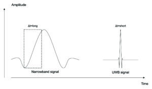
5. Time of Flight (ToF) or Time Difference of Arrival (ToA, TDoA)
A Time of Flight (ToF) positioning system uses a tight synchronization in all network nodes and records the traveling time between the object and all access points. As radio signals travel with the speed of light, it is possible to obtain very exact positioning if the synchronization source has the right resolution. As a rule of thumb, nanosecond synchronization gives sub-meter precision.
Proprietary ToF solutions have been implemented based on Wi-Fi, Bluetooth and 868MHz chipsets. All of these technologies come with quite a narrow spectrum bandwidth, resulting in a long symbol transmission time over the air. In the receiver, it can be problematic to detect the exact start of a frame, especially when we add noise and multipath propagation of radio signals to the equation. This results in timing issues for a ToF solution. Ultra Wideband (UWB), on the contrary, comes with channel bandwidths of more than 500 MHz and therefore has a very short symbol time which is easy to detect. This is illustrated in the figure below where we see the slow amplitude rise for the narrowband signal to the left and the faster, noise resistant UWB signal which provides much more stable means of synchronization to the right. Wider channel bandwidth is also used by mmW 5G networks.
9.3 Tracking technologies for indoor use cases
Most tracking systems are used to find or position objects either indoors or outdoors. The sections below cover the most common technologies used for each area. You can position things, tags, people, equipment and vehicles in indoor environments in many different ways. Most of the technologies covered below are further described in the Network chapter. We will begin by discussing options for indoor use cases.
9.3.1 Wi-Fi
Wi-Fi is available everywhere indoors and is therefore the perfect “macro” tracking solution for many environments. Existing infrastructure can be re-used for tracking and the IT department can keep supporting a single network. Wi-Fi chipsets are available in tablets, laptops and phones, allowing us to create visitor heatmaps or use the infrastructure for wayfinding. The precision provided by RSSI based Wi-Fi tracking systems is as mentioned above typically 3-10 meters given a proper network design, and this is more than adequate if we want to know whether a wheelchair or a bed is located on floor 14 of a hospital or if it is somewhere in the basement.
With fingerprinting or AoA, precision can be enhanced even further. Ability to measure round-trip-time (Time of Flight) is also supported in many Wi-Fi chipsets through the existing IEEE802.11mc and planned IEEE802.11az standards, but it is not yet well-adopted and requires proprietary location engine development to provide triangulation. Wi-Fi is also often combined with other technologies like Bluetooth, IR or ultrasound when the precision needs to be enhanced or when we want to avoid floor-hopping.
Wi-Fi is a power-hungry technology compared with some of the alternatives listed below, however, there is no problem running a properly configured Wi-Fi asset tag from a company like Centrak for one to two years before a battery swap is required. As mentioned earlier in this chapter, many Wi-Fi tags belong to the “RFID Wi-Fi” category and do not have to be authenticated to the Wi-Fi network, they just broadcast their packets containing the ID of the tag and sometimes telemetry data like a temperature or accelerator value. This enhances network security and improves the battery lifetime of the tags.
Examples of application areas where Wi-Fi is used include asset tracking in hospitals, people tracking in offices and industries, vehicle/truck tracking in production areas and people counting in retail and smart cities.
9.3.2 Bluetooth Low Energy (BLE)
BLE comes with lower output power and energy consumption than Wi-Fi but supports similar range thanks to its narrow frequency channels. RSSI based BLE solutions often provide better positioning precision than Wi-Fi, mainly due to the fact that the BLE chipsets are cheaper than Wi-Fi chipsets which means we can afford to build a lot more access points for the same money. As we mentioned earlier, more APs means shorter average distance between the tags and the infrastructure nodes, improving the RSSI tracking performance. The resolution of RSSI based positioning is highly dependent on how close we can get to the objects we want to track. It is not uncommon that Bluetooth based tracking systems come with a factor 5 to 10 more access points than Wi-Fi systems. The total cost of the hardware is similar, but each of these nodes need to be installed and sometimes they also need a power outlet or a LAN cable and a Power over Ethernet (PoE) switch port. This is a substantial part of the overall installation and hardware cost.
Many BLE based tracking systems are proprietary and sometimes based on AoA or ToF. This means we cannot take a tag from one vendor and make it work in another vendor’s system without changing the firmware of the chipset. The reason for this is that many tracking solutions are purpose-built to address specific use cases. One example is the elderly care bracelet from Nectarine Health which monitors the health of a person and streams it to a cloud service where the data is analyzed. For this bracelet to last for days, Nectarine had to develop their own BLE chipset firmware. Another example is the Finnish tracking provider Quuppa mentioned in the Network and Protocols chapter. Their solution is built on a proprietary AoA based BLE system which is capable of tracking things in real-time with sub-meter precision. Quuppa’s solutions are implemented by Nokia and delivered as part of their indoor 4G and 5G systems.
BLE based tracking often makes sense for smart office applications, in retail and for industrial applications up to a certain point. If we want to cover a full hospital or mine site, the network rollout and maintenance costs could be problematic as we either need to swap a large number of batteries from time to time, or we need to install a lot of LAN cables and PoE switches. Worth noting is that many Wi-Fi providers, including for example Cisco and HPE Aruba, are adding BLE support in their Wi-Fi APs. This is not only for tracking purposes but also to be able to support more IoT use cases.
9.3.3 Passive RFID
Radio Frequency Identification (RFID) comes with both active and passive tags. An active tag is powered by a battery while a passive tag is a simple transceiver without an own battery source. When a base station or scanner pings a passive tag, a tiny part of the transmitted energy is harvested in a capacitor in the tag and used when sending a response to the incoming message. This is a form of proximity-based positioning where the tag responds with its ID and sometimes some additional information. The limited and sporadic access to energy means passive RFID tags are seldomly able to initiate communication or to provide sensor data. They simply wait to be pinged and then respond.
The range of passive RFID is often below a centimetre when used in credit card systems, but it is possible to reach 10-15 meters or more with high gain antennas on the scanner side. Since the tags are simple and come without batteries, the price point is low, and RFID is often used to verify the authenticity, price or position of goods or to simplify inventory in retail, hospitals and factories.
9.3.4 Ultra Wideband (UWB)
Ultra Wideband offers sub-centimetre positioning precision in indoor environments and is a technology which has gained significant attention over the past years. UWB tags used to be expensive and there was no available ecosystem. Many new UWB-based tracking solutions are now available and companies like Ericsson and Cisco have plans to support UWB in their network products to enhance the precision in positioning for certain use cases.
UWB is ToF based, uses low power and can penetrate walls. A single access point can cover a few hundred square meters and three to four APs are typically needed to get good precision. UWB is used for high-resolution tracking in certain parts of hospitals, schools and industrial plants. We can expect to see many multimode asset tags in the future where Wi-Fi, Bluetooth or other RF standards provide macro-layer positioning and where UWB is used to add high-precision positioning for specific use cases.
9.3.5 Magnetic fields, ultrasound and IR
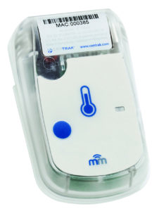
Short-range technologies such as magnetic fields, ultrasound and IR are all used to detect presence in a room, on a parking lot or similar. They are often used as a complement to Wi- Fi/BLE tracking in hospitals when room-level accuracy is required or when we want to avoid floor-hopping. The picture below shows a Multi-Mode Asset Tag from Centrak containing a combination of Wi-Fi for RSSI based macro tracking and IR for in-room presence detection.
9.3.6 Li-Fi
An LED based network, sometimes referred to as Li-Fi, connects devices with visible or infrared light via luminaires in the ceiling. Each LED can broadcast its own code or listen to the unique ID sent by a device. As a light transmitter does not need an amplifier, filters or costly patented radio frequency receivers, it has the potential to provide precise positioning of objects with affordable tags and extremely good battery life. This is a technology that is not yet widely adopted, but it has enormous potential and solutions are already available from organisations such as Signify.
9.3.7 4G and 5G
4G and 5G systems are not commonly used for indoor tracking due to the fact that these networks are often provided from outside masts, tags are expensive and energy consumption is high compared with unlicensed alternatives. When indoor networks are in place, they are normally built with large, passive Distributed Antenna Systems (DAS) which cannot support positioning due to that the entire indoor network more or less consists of a single antenna. This might change in the coming years as Private 4G and 5G networks are becoming commonplace in the enterprise and Industrial IoT areas. Many industrial companies are already looking at connecting vehicles, CCTV cameras, IoT devices and robots over 5G. An indoor small cell based 4G network could provide similar tracking resolution to Wi-Fi, with the added benefit of, unlike Wi-Fi, extending beyond building limits. 5G in mmWave bands supports very wide channel bandwidth and will over time be able to support similar resolution as UWB.
9.4 Tracking technologies for outdoor use cases
In outdoor environments, the Global Positioning System (GPS) is the preferred choice for most positioning and tracking solutions. A GPS receiver listens to a number of satellites, each tightly synchronized with each other. When the GPS receiver receives the time stamped packets from different satellites it can use the information to calculate its own latitude, longitude and altitude. The resulting position is often sent via 2G, 3G, 4G, or one of the LPWAN protocols described in the Network and Protocols chapter, to a backend service where the generated position is displayed or sent to applications providing fleet management services, pet tracking or similar.
While a GPS works everywhere outdoors regardless of weather conditions and comes without traffic costs, the chipsets are power-hungry and cannot hear the satellites when placed under a roof. The GPS signals sent from satellites are using low power and it can take up to several minutes for a receiver to find the satellites when scanning. There are ways of speeding this process up by combining the GPS with radio chipsets that can make an initial scan to get an approximate geographic position from a mobile network to help the GPS know which satellites to look for. However, this initial scan also requires energy, and if we cannot power the GPS from another source, we are reliant on battery power. For many trackers this means a battery change is necessary once or even several times per year depending on how frequently they report their position.
These battery constraints and the fact that GPS trackers do not work indoors have resulted in three alternative types of outdoor tracking methods.
● Radio network tracking
When the police are looking for a missing person or investigating a crime, they often ask mobile operators to provide location data about phones from their mobile masts. The resolution of this tracking could be anything from just a timestamp on a single mast to a quite precise position given by triangulation between several masts.
In mobile networks and LPWAN networks, devices can be triangulated based on signal strength. This works both indoors and outdoors, sometimes with a precision of 50-100 meters which often is good enough when tracking lifebuoys, boat engines or cattle. A lot of standardization and product development is going on in this area and we can expect to see more precise Time of Flight-based methods to become commonplace in the coming years.
● Proprietary RF trackers
Proprietary tracking systems are sometimes using the license free 2.4 GHz, 868 MHz or 915 MHz ISM bands to provide combined indoor and outdoor solutions for tracking and sensor networking. These networks could be built in mesh or star topology and support high-precision positioning via time of flight or angle of arrival methods. The solutions could be useful in construction zones or in a factory where specific requirements result in high demands on range and precision and where it is hard to set up the infrastructure nodes.
● Dual-radio trackers
GPS trackers backhauled by GSM, NB-IoT, LoRaWAN or Sigfox sometimes add Bluetooth or Wi-Fi support for indoor proximity location. As a result, a tagged car or box can be followed both outdoors and indoors throughout a post terminal building. This could be useful also for objects that do not move much, like a trailer sometimes standing under a roof for long periods of time. Some of these trackers also turn off the GPS when in proximity to a BLE beacon. This helps save battery lifetime on the tracker.
9.5 Combined and customized solutions
If you work as an IoT Solution Architect or System Integrator, you will run into situations where tracking solutions have to be customized. This is especially true for use cases where the environment and types of objects to be tracked impact how we can perform the tracking. As an example, let us assume we have a customer who manufactures plastic boxes of different models and sizes. During the manufacturing process, each box is labelled with a unique, passive RFID tag before it is placed outdoors in an open area.
To improve the inventory process, minimize warehouse picking time and simplify logistical processes, the customer wants to track each box on the way from manufacturing, via storage, to delivery. A Wi-Fi network is already in place in the area, but it has weak coverage and the customer wants to use disposable tags without batteries on all boxes. As the passive RFID tag is already placed on all boxes, we could suggest a tailored solution based on the following components:
● A truck-mounted RFID scanner with a directional antenna. This scanner could read passive RFID tags up to a few meters.
● A vehicle-mounted 4G/Wi-Fi router equipped with a GPS.
● A backend service where positions are stored and visualized, supporting data reporting.
The high-level solution is shown in the figure below.
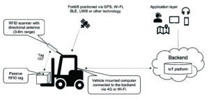
When an RFID tag is seen by the RFID scanner, the ID of the tag is sent to the vehicle computer which adds a timestamp, the GPS position of the truck and maybe other information gathered from the truck’s internal system. This information is sent to the backend any time there is a change of state in the tag detection. The result would be positioning data that the backend can use to calculate where the boxes were picked up and dropped off the last time they were seen.
This is a simple example of how different technologies could be combined when building IoT solutions or when testing things during a pilot phase. These tailored solutions often require code to be created to tie the different components together, and as the code has to be supported over time it could be worth looking for a ready-made solution before moving into a production environment.
9.6 Wrap-up and tips
Successful tracking and wayfinding solutions require in-depth knowledge of the people and objects you want to position and the environments where the positioning should take place. Consider the following questions:
● What is the required resolution for the positioning?
● How frequently should an object report its position?
● Is there any existing IT infrastructure (including cameras) we could use?
● What is the IT organization’s view of the infrastructure and related management systems?
● What does the ecosystem of tags, phones and other objects to position look like?
● What will the overall service model look like? Do we have to swap batteries from time to time and who is responsible for that?
● What kind of user interfaces are requested by the IT organization, by co-workers and by customers?
In short, a decent pre-study is key to maximising your chances of developing a successful solution.
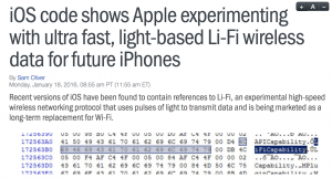
by bwireless | Jan 15, 2019 | 5G, Augmented Reality, Li-Fi, Wi-Fi, Wireless
Wireless transmission of information has been around for centuries. We are all used to connecting our smartphones, tablets and laptops over radio protocols such as Wi-Fi, 4G and Bluetooth. Over the past years, solutions for home automation, connected cars, smart cities and other Internet of Things (IoT) areas have raised awareness for other types of radio standards like Zigbee, LoRaWAN, NB-IoT and Z-wave.
The common denominator for these types of communication is that it is carried out on a very small chunk of the popular Radio Frequency (RF) spectrum which, in turn, is a fraction of the overall electromagnetic spectrum that spans not only RF but also various types of light, gamma rays and x-rays (see the figure below, borrowed from miniphysics.com) .
Li-Fi is a technology where light waves (rather than RF waves) are used as the communication medium. This is nothing new. In fact, visible light was used to carry information in some of the earliest semaphore and smoke signal wireless systems in history. Camera based IoT devices are often using the same spectrum.
In this article, we take a look at how Li-Fi works, its pros and cons, how likely it is that you have to swap your Wi-Fi router to LEDs in a couple of years and which applications/IoT areas where we expect to see a lot of Li-Fi in a not too distant future.

What is VLC, OWC and Li-Fi?
Optical Wireless Communication (OWC) refers to wireless communication over infrared (IR) light, visible light (VLC) or ultraviolet (UV) light. Applications using this spectrum today range from remote controls, video camera IoT solutions, tracking systems in healthcare, access networks and laser backhaul links. Li-Fi today normally refers to data being transmitted over visible light.
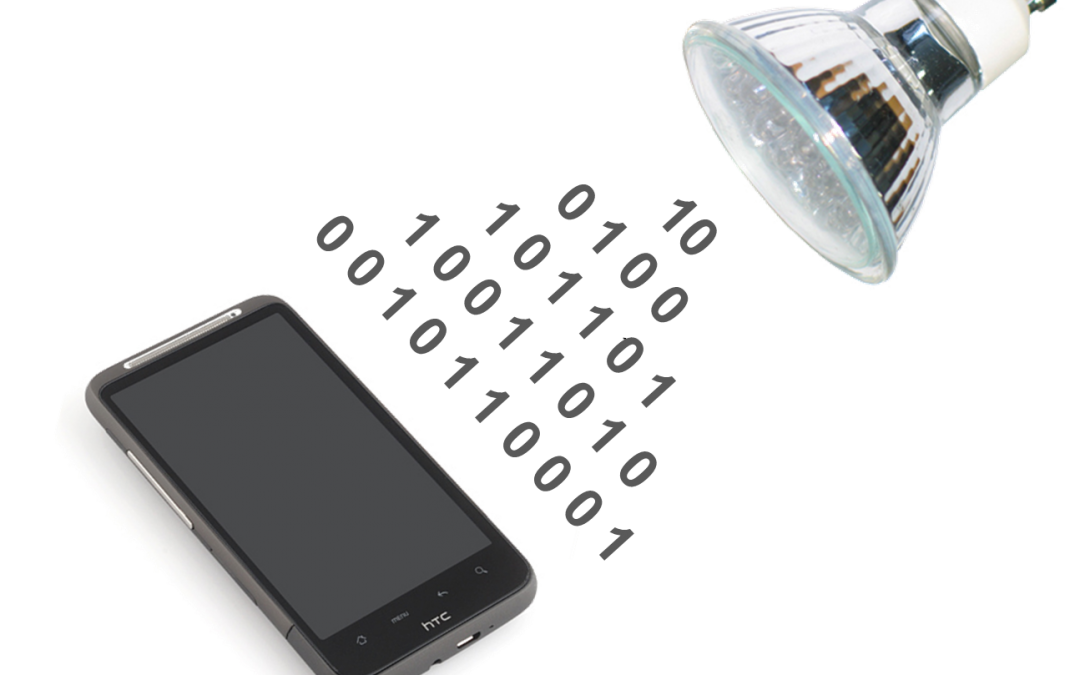
How does Li-Fi work?
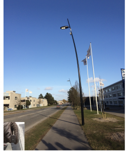
Just as RF based wireless solutions like 4G, Wi-Fi, 5G and Bluetooth, Li-Fi uses transmitters and receivers to communicate. The transmitter typically consists of Light Emitting Diodes (LEDs) of the same type you buy in your local store. It could also be the flash on your mobile phone, a LED display, the spotlight of a car, a traffic light or something else that emits light.
Data is modulated (by single or multi carrier techniques) by adjusting the brightness of the LED at a very rapid pace that is not noticeable by the human eye. With visible light, it is even possible to do this in a room that the human eye would experience as ”dark”. The receiver (which could be the camera on your phone) can register the differences in brightness and decode the transmitted signal even in full daylight. The figure below shows Li-Fi demonstrated from regular street lights in Denmark. The receiver in this demo system is shown in the bottom left corner of the figure.
Which benefits do Li-Fi bring over RF based wireless communication technologies?
Li-Fi brings some interesting things to the table:
- Massive throughput. Almost 10 Gbps peak rates have been demonstrated from a single light source.
- Much simpler and cheaper transmitters and receivers. Modulating light intensity does not require any radio front ends with amplifiers, filters and antennas. Less patent royalties have to be paid to chipset makers. As the result, Li-Fi is expected to be 10x cheaper than Wi-Fi.
- Extremely low energy consumption. This brings a lot of benefits to body-near devices like AR/VR glasses, watches, bracelets and badges where the battery lifetime is crucial for the end user experience.
- High security. Only if you can see the light you can ”hear” the communication.
- No RF pollution. As a Li-Fi transceiver does not emit RF waves, it does not generate Intermodulation Products, spurious emissions, noise or interference to RF equipment.
- Unlike for RF base stations and access points, you never have to find sites for LEDs. Those already exist.
What are the challenges for Li-Fi?
Li-Fi obviously requires the receiver to ”see” the light sent by the transmitter. It does not have to be line of sight, but the light has to be bright enough That is not the case with RF communication which often can traverse walls and other obstacles. The main problem for laser links, remote controls and Li-Fi is therefore that the signal path could be blocked by clothes, fog, snow or something else.
Another challenge is that you need backhaul to the LED armature. Albeit that could be a wireless link (over RF or light), a typical installation in an enterprise building or a hospital would require each armature to be backhauled by an Ethernet link (LAN cable or optical fiber). No problem in newer buildings, but it could be a retro-fit challenge.
Which are the typical application areas for Li-Fi?
Cheap transceivers, low power consumption, massive capacity and high security means Li-Fi will be extremely useful in certain areas. Examples:
- AR/VR glasses, watches and other gadgets that are not placed in a pocket and where battery lifetime is crucial for the user experience.
- Internet of Things applications. Here, Li-Fi can be an in-room carrier of data from battery-powered devices to a sensor platform placed in the ceiling, it can be used for tracking of gadgets in a hospital or factory, it can be used for indoor wayfinding and on-boarding of devices in a smart office. The fact that you easily can communicate with a LED display opens doors.
- Access networks in sensitive environments where security or RF pollution is unwanted. Airplanes, nuclear plants and hospitals are often mentioned.
Will Li-Fi replace Wi-Fi?
We need to divide Wi-Fi into two areas to be able to answer that:
- Traditional Wi-Fi access points operating at 2.4GHz and 5GHz. The same type that you have at home and in your office today. These were once created in order for average Joe to be able to very easily cover an apartment or mid-sized American house from the point where the cable modem entered the building. Doing the same with Li-Fi would require cables to every room and an army of electricians.
- Then we have the new type of Wi-Fi standards operating at 60GHz. We often refer to this as ”WiGig”, and it differs from traditional Wi-Fi in two ways:
- Enormous bandwidth.
- The higher frequency makes it very hard for signals to penetrate walls. Good as you will not hear your neighbors network, but it also means you need one WiGig AP per room where you need capacity.
Since WiGig is created for short-range, high capacity, in-room use cases, it is much more prone to competition from Li-Fi. If we compare the two technologies, we expect Li-Fi to come out both cheaper and a lot more flexible (pre-integrated in cameras, LED screens etc.) over time.
Li-Fi is an extremely potential technology that we expect a lot from in the coming years. We will follow this space closely.
Main image source: visiblelightcomm.com

by bwireless | Jan 1, 2019 | Internet of Things (IoT), Platforms
If you have any plans getting involved with the Internet of Things (IoT), chances are that you will come across the term “IoT platforms”. This article describes some of the most common questions regarding these platforms, such as what they are used for, how they differ from each other and what you should consider before selecting one.
Which role does an IoT platform play in the overall IoT architecture?
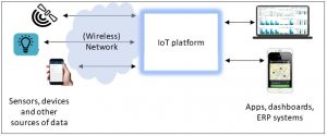
IoT spans a lot of areas, but most IoT solutions have four major building blocks in common:
1) Data collection (via sensors, devices, gateways, APIs, humans etc.).
2) Some (wireless) infrastructure or network to transmit the data from the sensor.
3) An IoT platform where data is collected, analyzed and from where devices often can be managed to some extent.
4) An application layer (dashboard, mobile app, API for integration to other systems, services platform, ERP or sales systems etc.).
What else can an IoT platform do?
Apart from the basic stuff described above, many IoT platforms can also do a lot of other tricks. Examples:
– Store, normalize and filter data.
– Represent data sources and objects/humans/places in logical object models.
– Analyze and build logics between the collected data to automate a process, create an alarm etc. based on rules that you can define yourself.
– Present data in dashboards/maps/portals or publish it through (open or industry-specific) Application Programming Interfaces (APIs).
– Perform device management of sensors, devices and gateways.
– Manage and monitor (SIM) connectivity and data plans.
– Perform more advanced cognitive tasks, AI and machine learning based on collected data. This is sometimes offered as modules.
– Offer connectivity plan and subscription management, especially for SIM cards.
– Offer multi-tenancy support so that you can define who should get access to what kind of data.
– Billing management.
Why is the IoT platform landscape complex to understand?
Some platforms can provide a lot of the above described functionality in a very narrow way, some focus on just a few aspects, some are only handling network connectivity while other platforms actually are not platforms but Lego boxes with platform pieces that you can use to build something of. Some platforms support industry standard protocols like FIWARE or FHIR. Most platforms are created for vertical reasons (see below). All platforms are mixed up in comparison matrixes for various reasons. Any platform comparison should always come with a clear definition of what is compared, but that is seldom the case. As the result, you often end up looking at fruit salads rather than apple vs. apple comparisons.
What does “vertical platform” mean?
Unlike the “regular” fixed/mobile Internet, IoT is not standards driven but application driven. Most platforms are therefore originally created for specific purposes, like optimization of an industrial process, a home burglar system, asset tracking in a hospital or disruption of the taxi industry. We refer to these platforms as “vertical” as they target specific use cases or areas. A vertical platform comes with a well-defined ecosystem of supported devices, sensors and gateways from certain vendors. These platforms are seldomly interconnected to other vertical platforms (IoT really means Intranet of Things in most cases). As there are no well-spread open standards for device management, adding more sensors to a vertical platform later on may be costly in time and pesos. Vertical platform integration (for IoT or anything else) often gets exponentially complex with the number of involved systems. The reason is that API integration is a per-platform game due to poor standardization.
While vertical platforms often solve the tasks they are created for, they also come with scalability issues and lock-in effects. When you go for a vertical solution, always take the northbound APIs into consideration. You should be able to not only receive data from a vertical solution, but ideally also have device management control. A simple example is a street light system where you want to be able to not only read out data from the lights but also be able to dim them and turn them on and off. If you are a municipality or a large corporation, specifying the APIs here as part of a procurement process is key to be able to grow with solutions over time. It is actually more important than the platform selection. Also look out for any platform provider who is charging “per device” and/or “per Byte of storage”. Those kinds of models work well in proof of concepts, but you could end up with a non-scalable and costly infrastructure in the end.
I have heard about horizontal platforms. What is that?
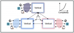
The main task for a horizontal platform is to aggregate and cross-connect verticals and by that also allow for data to be shared between systems in a scalable way.
The figure below shows the concepts of a horizontal platform. As each vertical only has one integration with the horizontal layer, this results in linear complexity when verticals are added, and suddenly it is possible to scale. New services can seamlessly be added and immediately reach entire populations.
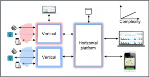
Horizontal platforms are often used to aggregate vertical platforms within Smart Cities, Smart Buildings, Healthcare etc. The purpose is not only for the application layer to get access to data in an easier and more scalable way, but it also allows logics to be built between verticals without the operator having to do stuff in many systems.
Horizontal platforms are often built with the Lego bricks provided by Microsoft, AWS or Google and can therefore also natively provide dashboards, cognitive functionality, machine learning and much more over time. During 2018 we saw several very capable open source platforms emerging. This will over time remove “per device and per Byte” cost for collecting data from sensors.
A properly built horizontal platform is the foundation for a scalable platform economy that can enable enormous values for a city, a hospital, a population or an entire nation. A good example is the X-Road system which is the (Blockchain based) e-health backbone for both Estonia and Finland.
Now, can you tell me which platform I should choose?
As the bullets above hopefully have described, various platforms solve different tasks and are created for different purposes. There is not one size fits all, and it is not possible to tell which vertical platform that is most suitable for a specific application or task without knowing what that application looks like. A general recommendation is to look at the open source communities early in a process. Several such platforms are very mature and allows you to start off building business from day one rather than spending time on development.
Another important thing to consider is that a lot of people who today are spending time on IoT probably instead should focus on the foundation of data collection and define what APIs should look like. If your patient data ends up in 20 different healthcare systems that you cannot access, you will never be able to use that data in an efficient and innovative way regardless of platform choice.
And that sums up where you should always start with IoT. Before picking a platform, a radio standard or a sensor you need to understand the use cases, business cases, problems to be solved, opportunities, humans, needs, business impact analysis and much more. Too often things are done the other way around.

by bwireless | Dec 28, 2018 | Internet of Things (IoT), LPWAN, Platforms
1. “50 billion connected devices” has already happened
Some say there will be 50 billion connected devices in 2025. It has already happened. Everything from cars and Barilla pasta to Nespresso capsules and Gillette razors are already connected and powered by IoT. Uber’s entire business model is built on an IoT platform. Your phone is probably part of tens or hundreds of IoT business models depending on how many apps you have installed.
2. Most devices will never be connected to the Internet
Unlike the previous “versions” of the Internet (content/people/mobile) that have been driven by standardization and certification, IoT is completely application driven. This has resulted in countless jungles of proprietary wireless techniques, protocols, platforms and applications that are tailored for various use cases but cannot talk to each other. Device communication outside your own IoT network is rare which is fine as there is generally no value in connecting your dog to a meeting room at the office or a fan system in a building to a car. IoT generally means Intranets of Things.
3. IoT Business Intelligence never gets better than the data you collect
Ok, you knew this already but it still needs to be highlighted. There are air quality sensors not capable of measuring data at a relevant resolution and energy meters that sit inside metal boxes in people’s basements without ability to get a wireless signal. If you cheat on radio front end, antenna design, network design, security or sensor quality it will bite back. Advice: Do not cheat.
4. You might already have access to the data you need
Example: A municipality could dig down hundreds of thousands of on-street parking sensors all over a city, or they could invest the money in a mobile payment platform like EasyPark that can provide the parking status via an API. No sensors, no hassle, just data, and at the same time they get rid of the parking ticket payment machines. The same applies for buildings, healthcare and a lot of other areas where sensor technology already exist. Before you roll out sensors or build a network, carefully consider if there is a smarter way of collecting the data.
5. IoT might be the next millennium bug
Pretty much every device is advertised with a maximum battery life time of ten years, and a lot of IoT systems are sold without lifecycle management support. Will all sensors we roll out today have been replaced by something else in ten years’ time or are we creating a new massive “millennium” bug when everything stops working in 2027? Many wireless networks will be gone ten years from now and sensor technology evolves all the time. It does not hurt to have a long-term plan.
6. A lot of sensors will soon be replaced by something else
The exponential technical evolution results in new technology reaching a lot of users faster than before, but also that technology gets outdated much quicker. VHS, CD and mp3 are good examples. Cameras and image recognition will replace a lot of sensor technology sooner than we think. As mentioned above, parking sensors can often be replaced by a software API. There are other concepts too, like synthetic sensors that potentially can replace a lot of legacy in-home sensors and at the same time increase security. Augmented Reality will replace many indoor positioning services where the aim is to find something. And on it goes.
7. The location of connected devices and sensors is more important than you expect
At a first glance, knowing the exact position/location of a device or sensor is only important if you are dealing with tracking/positioning of objects. However, if you automatically get the position of something it simplifies inventory, support and troubleshooting, and this can prove to be worth a lot for the TCO. Consider an activity based office where sensors with 5-10 years battery lifetime are spread out under tables, on trash bins and in meeting rooms. Will you refurnish, re-organize or move to another office during the coming five-ten years? Probably, and unless you are planning to arrange a massive “sensor hunt” for your staff, make sure you take measures. You get similar benefits when streetlights, parking sensors, water meters and other things report their position automatically.
8. IoT is about ecosystems. Be an attractive partner.
There are a lot of companies out there trying to figure out how they should be relevant in the IoT space. Many of them create own platforms, boxed solutions or develop own and very proprietary protocols. Most of them reinvent the wheel. A better approach is to stick to what they do best and refine that even further while joining ecosystems where their piece of the puzzle fits. Example: If your core business is to analyze a certain type of medical disease, do not employ backend coders to build a platform for this. Someone else has already spent 30 000 man hours to productify something that works. Instead, employ doctors and spend time with patients to build value in your algorithms.
9. Small scale is not the same as large scale
During 2018, tons of small-scale IoT Proof of Concepts (POCs) have been carried out all over the world. In many cases, some Low Power Wide Area Network (LPWAN) technology such as LoRaWAN has been used as the bearer of sensor data. Many of these POCs will scale up during 2019 and onwards, and that is when new types of issues will arise. The LoRaWAN ecosystem is scattered. Narrowband IoT comes with battery constrains. The 868MHz frequency band is very small without any guaranteed sustainable future, especially in larger cities. Provisioning of devices, distribution of security keys and certificates, platforms and their price plans, quality of sensors, precision in sensor measurements and much more will be very different when scaled up.
10. Your biggest IoT challenge is not technical
The evolution curve of technology has surpassed the pace of human adaptation rate and the result is that legacy processes and procurement processes, laws, politics and poor business impact analysis block innovation. We all see this daily when we buy new technology that comes with a massive engine under the hood while the user experience still is an old bicycle. A tender process (from RFI to purchase order) can take several years, and when it is time to buy in to something it is already outdated technology. To get things going, do not focus on technology but business operations, people, needs and user experience and set measurable goals for your IoT projects.