
This is a sample chapter taken from the book “Things you should know about the Internet of Things” which was released by bwireless in 2020. Pictures, reviews and more information about the book can be found here.
9. Tracking and wayfinding
On the surface, knowing the exact position/location of a device or sensor is only important if you are trying to find that object. However, looking deeper, if you automatically know the position of a device installed in the field you can simplify inventory, support and troubleshooting. This can prove to be invaluable for the Total Cost of Ownership (TCO) of your IoT business model.
As an example, consider an activity-based office solution where sensors are placed under tables and in conference rooms to detect the presence of people. When installing these devices, they are tied to a position on a map, and this process is manual if the devices cannot be automatically located by the network. Will the office space be refurnished during the contract period? Will batteries have to be replaced on some of the devices? Will the company reorganize and move people between floors or buildings? If the answer is yes to any of these questions, the provider of the activity-based office solution would end up with a much better service model if they did not have to visit the office and hunt down all devices from time to time. Similar benefits are obtained when streetlights, parking sensors, water meters, industrial robots and other things report their position automatically.
When tracking items or people, the network layer in the IoT stack often melds together with the device/sensor layer. The network acts as a sensor when hunting for devices. For this reason, IoT solutions built to position objects or humans come with very specific requirements on which network protocols to use.
In this chapter we look at:
● An overview of what we mean by tracking and wayfinding.
● The components and methods used by positioning systems.
● Common technologies used by indoor and outdoor wayfinding and tracking systems.
9.1 Tracking and wayfinding overview
Although the human brain is highly intelligent and comes with a good visual memory, most people spend time every day looking for lost things or simply trying to find their way around. We commonly use Google maps or custom apps in areas like malls or stadiums, and these tools are relying on various radio protocols to position people and objects.
9.1.1 Terminology
It is important to first make some distinctions in terminology.
● Positioning
Positioning refers to determining the location of an object indoors or outdoors. If the object to position is ourselves, we often rely on maps, signs or a GPS based app. When positioning objects, GPS, cameras, QR codes or wireless networks are commonly used.
● Wayfinding and blue dots
Wayfinding is how we find the way from A to B. A simple example is when we look at digital or analogue signs or when we type in an address in Google Maps and get instructions on how to get to the destination.
If we look at Google Maps in our phones, we see a blue dot showing where we are. This is the position calculated by the device. It is also possible to generate blue dot maps indoors, and they typically come with location-specific apps for wayfinding in areas such as offices and hospitals. Google has also added blue dot support in many public areas including airports and malls.
● Tracking
While wayfinding aims to provide information about where we are and where we are going, a tracking solution helps finding pets, children, goods, wheelchairs, cars and other objects and living creatures in various environments. Tracking can also be used when analyzing behaviors, or to build knowledge about how to plan out, for example, an airport or a shopping street in a city.
● Proximity
Proximity simply means being close to something. In many cases, knowing if you are close to an object is precisely the information we need – this is what solutions like Apple’s iBeacons or Tile are used for. If a customer is close to a product in a store, we can send a notification about an offer via an app. If we are looking for car keys, it is often enough to know whether they are in the car or if we left them inside of the house. We cover both tracking and wayfinding solutions in this chapter.
9.1.2 Which resolution is required when positioning an object?
As for most IoT solutions, it is important to spend time understanding what kind of precision is required to achieve a desired tracking effect. If we want to know where a missing child is located in a forest, 50 meters tracking resolution is probably good enough. If the same child gets lost during a big outdoor concert, +/- 50 meters is quite a lot and we might need something more detailed. If we are looking for a specific pallet with goods in a warehouse, we could get away with a proximity solution telling which part of the building these kinds of pallets are located, but it could also be relevant to get down to sub-meter resolution. A doctor looking for medical instruments in an emergency room may require centimetre precision and 3D resolution. It all depends on the use case. The defined resolution of the tracking sets the scene for what the technical solution has to look like.
Higher than required resolution drives unnecessary cost while insufficient resolution misses the target and makes the tracking solution useless.
9.1.3 Wayfinding today and tomorrow
Most wayfinding solutions today are based on some form of well-known radio technology such as GPS, Wi-Fi or Bluetooth. However, some other options are on the rise:
● Phone based Augmented Reality apps can use the camera and image recognition to provide excellent tracking resolution while at the same time adding a marketing layer of information in the picture. Consider a grocery store where you first get an exact route to the pasta and once you are there an inspirational video pops up showing a delicious dish.
● Cameras are quickly evolving and are today already used in many indoor tracking solutions. Cameras for counting people or undertaking pattern recognition could be placed in the ceiling and give exact information about how people move around a store or in a building. This solution has been implemented in airports and offices with great results. A surveillance camera system in a hospital could not only tell where beds and wheelchairs are located but also give additional useful information such as bed occupancy, or identification of faulty equipment such as a broken wheelchair. A surveillance camera system in a parking lot could be used to detect which paths cars are taking in the area.
● While most wayfinding applications today are visual, user interfaces based on audio are also emerging. This is not only useful for visually impaired people, but it also removes the need to install apps and to have a network connection on your device. An audio-based interface would use a wayfinding solution and present directions via sound rather than visually.
9.2 Wayfinding and tracking components
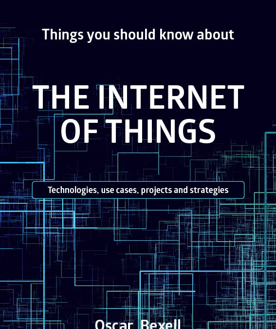
Most tracking solutions mimic our four-layer IoT stack and consist of the following components shown in the figure below.
● Things: Tags, sensors and devices
A tag is configured to send out a message containing the device ID and potentially telemetry data like temperature values, accelerator information or battery charging status, at regular time intervals. Commonly in Wi-Fi networks, the tags do not always connect to the network, they might just broadcast their ID and additional information and then it is up to the network to capture the information. This is often referred to as an “RFID tag” by the Wi-Fi community, which should not be confused with the passive RFID tags described later in this chapter. Any IoT device coming with a wireless chipset could in theory also be tracked by the wireless infrastructure.The actual resolution depends on how the wireless network is built and which features it comes with.
● Network
An asset tracking network can either be an existing grid of base stations or access points based on 4G, Wi-Fi or other existing nodes. It could also be a purpose-built tracking network. In those cases, the network nodes are often referred to as “base stations”, “observers”, “locators” or something else, and they come with their own management system.
● Location engine
This is our platform layer where the actual location of objects is calculated and where network nodes could be managed.
● Application layer
For tracking and wayfinding solutions, graphical user interfaces are of course common in the application layer, but depending on what is positioned it could also be a fleet management system, an inventory system or, as mentioned above, an audio-based interface.
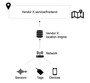
9.2.1 Network centric and device centric tracking methods
A Radio Frequency (RF) based tracking solution can be network centric or device centric. In a network centric approach, the device (or tag) sends out a data packet that the network uses when triangulating the position of the device. This is commonly used for asset tracking solutions where devices can be simpler and need to survive for years on a small battery. In a device centric solution, the device instead listens to the network and tries to figure out where it is based on what it can hear. This is how a GPS receiver and most phone-based wayfinding systems work.
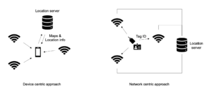
9.2.2 Radio frequency positioning methods
Once we have a network in place, we can use different methods to figure out where our devices or tags are located. The figure below shows the difference between the most common alternatives. All five methods are described below.
1. Proximity (presence detection)
In many IoT use cases we are only interested in simply knowing if an object is in a defined area or not. In this instance a proximity-based solution could be what we are looking for. Scanning of instruments in hospitals, location-based advertisement in stores and passage systems are often based on proximity with short-range RF protocols.
2. Received Signal Strength Indicator (RSSI) based positioning
Network nodes like access points, observers or locators are listening for incoming packets sent from devices and tags, and for each packet the signal strength is recorded by all nodes. This information is sent to the location engine which uses the information when triangulating the position of the object.
The challenge with RSSI based positioning is that the signal strength is reduced with the square of the distance from an object, and the quality is degraded by reflections and attenuated when traversing through various materials. Any time we double the distance between the tracked object and a network node, the signal level drops by at least 75%. This means that RSSI positioning is often unreliable unless the network nodes (for example Wi-Fi access points) are placed closely together. In environments where reflective metal objects are present, the calculated position can often jump around both horizontally and vertically and result in “floor-hopping” which means a positioned object could end up on the wrong floor in the user interface. Common resolution in RSSI based Wi-Fi and Bluetooth positioning systems is often 3-10 meters if we design these networks properly, but if there is a lot of metal or open atriums the precision could quickly be degraded.
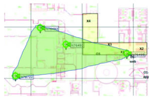
A good rule of thumb is to place the base stations (or access points) fairly close to each other (8-10 meters for Wi-Fi, 5-10 meters for Bluetooth) and use the “rubber band principle” shown in the figure below when designing the network. If we place an imaginary rubber band around the network nodes, the green-shaded area covered by the band is where we will have decent resolution in our tracking. This means we typically want to push the APs further out to the corners of the building, unlike traditional Wi-Fi access networks where APs are more centralized.
3. Fingerprinting
If we want to increase the precision and reliability of an RSSI based solution, we can consider using a method called fingerprinting. The idea is to perform walk tests in the tracking area, stopping every few meters to measure what the radio environment looks like and then store this into a fingerprint database. Later on, when a device wants to find its location, it scans the radio environment and uses the result to query the database which can be located either in the device, in the location engine or in a backend service.
Fingerprinting could increase accuracy of a tracking solution by up to several meters and help avoid floor-hopping, but it also requires new walk tests from time to time to ensure the lookup-table is accurate. In Wi-Fi environments, solutions from Aeroscout/Ekahau make use of fingerprinting for both healthcare and industrial applications. Google uses a similar technology when providing indoor wayfinding support in Google Maps.
4. Angle of Arrival (AoA)
In indoor locations that are open and come with ceiling heights of 5-6 meters or more, it could be worth considering an Angle of Arrival (AoA) positioning method rather than one based on RSSI. In an AoA network, the access points are equipped with antenna arrays that can measure the time difference of incoming signals and filter out copies generated by multipath propagation. The result is that the accuracy of the positioning can be improved to below one meter. AoA positioning is not dependent on the signal strength of an incoming packet, it only looks at the delta between bouncing copies of the same signal and picks the first incoming contribution which is expected to be the line of sight version.
5. Time of Flight (ToF) or Time Difference of Arrival (ToA, TDoA)
A Time of Flight (ToF) positioning system uses a tight synchronization in all network nodes and records the traveling time between the object and all access points. As radio signals travel with the speed of light, it is possible to obtain very exact positioning if the synchronization source has the right resolution. As a rule of thumb, nanosecond synchronization gives sub-meter precision.
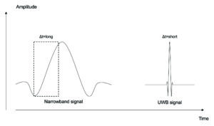
Proprietary ToF solutions have been implemented based on Wi-Fi, Bluetooth and 868MHz chipsets. All of these technologies come with quite a narrow spectrum bandwidth, resulting in a long symbol transmission time over the air. In the receiver, it can be problematic to detect the exact start of a frame, especially when we add noise and multipath propagation of radio signals to the equation. This results in timing issues for a ToF solution. Ultra Wideband (UWB), on the contrary, comes with channel bandwidths of more than 500 MHz and therefore has a very short symbol time which is easy to detect. This is illustrated in the figure below where we see the slow amplitude rise for the narrowband signal to the left and the faster, noise resistant UWB signal which provides much more stable means of synchronization to the right. Wider channel bandwidth is also used by mmW 5G networks.
9.3 Tracking technologies for indoor use cases
Most tracking systems are used to find or position objects either indoors or outdoors. The sections below cover the most common technologies used for each area. You can position things, tags, people, equipment and vehicles in indoor environments in many different ways. Most of the technologies covered below are further described in the Network chapter. We will begin by discussing options for indoor use cases.
9.3.1 Wi-Fi
Wi-Fi is available everywhere indoors and is therefore the perfect “macro” tracking solution for many environments. Existing infrastructure can be re-used for tracking and the IT department can keep supporting a single network. Wi-Fi chipsets are available in tablets, laptops and phones, allowing us to create visitor heatmaps or use the infrastructure for wayfinding. The precision provided by RSSI based Wi-Fi tracking systems is as mentioned above typically 3-10 meters given a proper network design, and this is more than adequate if we want to know whether a wheelchair or a bed is located on floor 14 of a hospital or if it is somewhere in the basement.
With fingerprinting or AoA, precision can be enhanced even further. Ability to measure round-trip-time (Time of Flight) is also supported in many Wi-Fi chipsets through the existing IEEE802.11mc and planned IEEE802.11az standards, but it is not yet well-adopted and requires proprietary location engine development to provide triangulation. Wi-Fi is also often combined with other technologies like Bluetooth, IR or ultrasound when the precision needs to be enhanced or when we want to avoid floor-hopping.
Wi-Fi is a power-hungry technology compared with some of the alternatives listed below, however, there is no problem running a properly configured Wi-Fi asset tag from a company like Centrak for one to two years before a battery swap is required. As mentioned earlier in this chapter, many Wi-Fi tags belong to the “RFID Wi-Fi” category and do not have to be authenticated to the Wi-Fi network, they just broadcast their packets containing the ID of the tag and sometimes telemetry data like a temperature or accelerator value. This enhances network security and improves the battery lifetime of the tags.
Examples of application areas where Wi-Fi is used include asset tracking in hospitals, people tracking in offices and industries, vehicle/truck tracking in production areas and people counting in retail and smart cities.
9.3.2 Bluetooth Low Energy (BLE)
BLE comes with lower output power and energy consumption than Wi-Fi but supports similar range thanks to its narrow frequency channels. RSSI based BLE solutions often provide better positioning precision than Wi-Fi, mainly due to the fact that the BLE chipsets are cheaper than Wi-Fi chipsets which means we can afford to build a lot more access points for the same money. As we mentioned earlier, more APs means shorter average distance between the tags and the infrastructure nodes, improving the RSSI tracking performance. The resolution of RSSI based positioning is highly dependent on how close we can get to the objects we want to track. It is not uncommon that Bluetooth based tracking systems come with a factor 5 to 10 more access points than Wi-Fi systems. The total cost of the hardware is similar, but each of these nodes need to be installed and sometimes they also need a power outlet or a LAN cable and a Power over Ethernet (PoE) switch port. This is a substantial part of the overall installation and hardware cost.
Many BLE based tracking systems are proprietary and sometimes based on AoA or ToF. This means we cannot take a tag from one vendor and make it work in another vendor’s system without changing the firmware of the chipset. The reason for this is that many tracking solutions are purpose-built to address specific use cases. One example is the elderly care bracelet from Nectarine Health which monitors the health of a person and streams it to a cloud service where the data is analyzed. For this bracelet to last for days, Nectarine had to develop their own BLE chipset firmware. Another example is the Finnish tracking provider Quuppa mentioned in the Network and Protocols chapter. Their solution is built on a proprietary AoA based BLE system which is capable of tracking things in real-time with sub-meter precision. Quuppa’s solutions are implemented by Nokia and delivered as part of their indoor 4G and 5G systems.
BLE based tracking often makes sense for smart office applications, in retail and for industrial applications up to a certain point. If we want to cover a full hospital or mine site, the network rollout and maintenance costs could be problematic as we either need to swap a large number of batteries from time to time, or we need to install a lot of LAN cables and PoE switches. Worth noting is that many Wi-Fi providers, including for example Cisco and HPE Aruba, are adding BLE support in their Wi-Fi APs. This is not only for tracking purposes but also to be able to support more IoT use cases.
9.3.3 Passive RFID
Radio Frequency Identification (RFID) comes with both active and passive tags. An active tag is powered by a battery while a passive tag is a simple transceiver without an own battery source. When a base station or scanner pings a passive tag, a tiny part of the transmitted energy is harvested in a capacitor in the tag and used when sending a response to the incoming message. This is a form of proximity-based positioning where the tag responds with its ID and sometimes some additional information. The limited and sporadic access to energy means passive RFID tags are seldomly able to initiate communication or to provide sensor data. They simply wait to be pinged and then respond.
The range of passive RFID is often below a centimetre when used in credit card systems, but it is possible to reach 10-15 meters or more with high gain antennas on the scanner side. Since the tags are simple and come without batteries, the price point is low, and RFID is often used to verify the authenticity, price or position of goods or to simplify inventory in retail, hospitals and factories.
9.3.4 Ultra Wideband (UWB)
Ultra Wideband offers sub-centimetre positioning precision in indoor environments and is a technology which has gained significant attention over the past years. UWB tags used to be expensive and there was no available ecosystem. Many new UWB-based tracking solutions are now available and companies like Ericsson and Cisco have plans to support UWB in their network products to enhance the precision in positioning for certain use cases.
UWB is ToF based, uses low power and can penetrate walls. A single access point can cover a few hundred square meters and three to four APs are typically needed to get good precision. UWB is used for high-resolution tracking in certain parts of hospitals, schools and industrial plants. We can expect to see many multimode asset tags in the future where Wi-Fi, Bluetooth or other RF standards provide macro-layer positioning and where UWB is used to add high-precision positioning for specific use cases.
9.3.5 Magnetic fields, ultrasound and IR
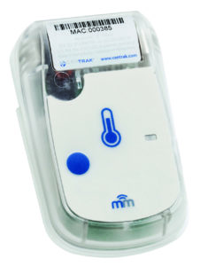
Short-range technologies such as magnetic fields, ultrasound and IR are all used to detect presence in a room, on a parking lot or similar. They are often used as a complement to Wi- Fi/BLE tracking in hospitals when room-level accuracy is required or when we want to avoid floor-hopping. The picture below shows a Multi-Mode Asset Tag from Centrak containing a combination of Wi-Fi for RSSI based macro tracking and IR for in-room presence detection.
9.3.6 Li-Fi
An LED based network, sometimes referred to as Li-Fi, connects devices with visible or infrared light via luminaires in the ceiling. Each LED can broadcast its own code or listen to the unique ID sent by a device. As a light transmitter does not need an amplifier, filters or costly patented radio frequency receivers, it has the potential to provide precise positioning of objects with affordable tags and extremely good battery life. This is a technology that is not yet widely adopted, but it has enormous potential and solutions are already available from organisations such as Signify.
9.3.7 4G and 5G
4G and 5G systems are not commonly used for indoor tracking due to the fact that these networks are often provided from outside masts, tags are expensive and energy consumption is high compared with unlicensed alternatives. When indoor networks are in place, they are normally built with large, passive Distributed Antenna Systems (DAS) which cannot support positioning due to that the entire indoor network more or less consists of a single antenna. This might change in the coming years as Private 4G and 5G networks are becoming commonplace in the enterprise and Industrial IoT areas. Many industrial companies are already looking at connecting vehicles, CCTV cameras, IoT devices and robots over 5G. An indoor small cell based 4G network could provide similar tracking resolution to Wi-Fi, with the added benefit of, unlike Wi-Fi, extending beyond building limits. 5G in mmWave bands supports very wide channel bandwidth and will over time be able to support similar resolution as UWB.
9.4 Tracking technologies for outdoor use cases
In outdoor environments, the Global Positioning System (GPS) is the preferred choice for most positioning and tracking solutions. A GPS receiver listens to a number of satellites, each tightly synchronized with each other. When the GPS receiver receives the time stamped packets from different satellites it can use the information to calculate its own latitude, longitude and altitude. The resulting position is often sent via 2G, 3G, 4G, or one of the LPWAN protocols described in the Network and Protocols chapter, to a backend service where the generated position is displayed or sent to applications providing fleet management services, pet tracking or similar.
While a GPS works everywhere outdoors regardless of weather conditions and comes without traffic costs, the chipsets are power-hungry and cannot hear the satellites when placed under a roof. The GPS signals sent from satellites are using low power and it can take up to several minutes for a receiver to find the satellites when scanning. There are ways of speeding this process up by combining the GPS with radio chipsets that can make an initial scan to get an approximate geographic position from a mobile network to help the GPS know which satellites to look for. However, this initial scan also requires energy, and if we cannot power the GPS from another source, we are reliant on battery power. For many trackers this means a battery change is necessary once or even several times per year depending on how frequently they report their position.
These battery constraints and the fact that GPS trackers do not work indoors have resulted in three alternative types of outdoor tracking methods.
● Radio network tracking
When the police are looking for a missing person or investigating a crime, they often ask mobile operators to provide location data about phones from their mobile masts. The resolution of this tracking could be anything from just a timestamp on a single mast to a quite precise position given by triangulation between several masts.
In mobile networks and LPWAN networks, devices can be triangulated based on signal strength. This works both indoors and outdoors, sometimes with a precision of 50-100 meters which often is good enough when tracking lifebuoys, boat engines or cattle. A lot of standardization and product development is going on in this area and we can expect to see more precise Time of Flight-based methods to become commonplace in the coming years.
● Proprietary RF trackers
Proprietary tracking systems are sometimes using the license free 2.4 GHz, 868 MHz or 915 MHz ISM bands to provide combined indoor and outdoor solutions for tracking and sensor networking. These networks could be built in mesh or star topology and support high-precision positioning via time of flight or angle of arrival methods. The solutions could be useful in construction zones or in a factory where specific requirements result in high demands on range and precision and where it is hard to set up the infrastructure nodes.
● Dual-radio trackers
GPS trackers backhauled by GSM, NB-IoT, LoRaWAN or Sigfox sometimes add Bluetooth or Wi-Fi support for indoor proximity location. As a result, a tagged car or box can be followed both outdoors and indoors throughout a post terminal building. This could be useful also for objects that do not move much, like a trailer sometimes standing under a roof for long periods of time. Some of these trackers also turn off the GPS when in proximity to a BLE beacon. This helps save battery lifetime on the tracker.
9.5 Combined and customized solutions
If you work as an IoT Solution Architect or System Integrator, you will run into situations where tracking solutions have to be customized. This is especially true for use cases where the environment and types of objects to be tracked impact how we can perform the tracking. As an example, let us assume we have a customer who manufactures plastic boxes of different models and sizes. During the manufacturing process, each box is labelled with a unique, passive RFID tag before it is placed outdoors in an open area.
To improve the inventory process, minimize warehouse picking time and simplify logistical processes, the customer wants to track each box on the way from manufacturing, via storage, to delivery. A Wi-Fi network is already in place in the area, but it has weak coverage and the customer wants to use disposable tags without batteries on all boxes. As the passive RFID tag is already placed on all boxes, we could suggest a tailored solution based on the following components:
● A truck-mounted RFID scanner with a directional antenna. This scanner could read passive RFID tags up to a few meters.
● A vehicle-mounted 4G/Wi-Fi router equipped with a GPS.
● A backend service where positions are stored and visualized, supporting data reporting.
The high-level solution is shown in the figure below.
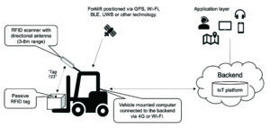
When an RFID tag is seen by the RFID scanner, the ID of the tag is sent to the vehicle computer which adds a timestamp, the GPS position of the truck and maybe other information gathered from the truck’s internal system. This information is sent to the backend any time there is a change of state in the tag detection. The result would be positioning data that the backend can use to calculate where the boxes were picked up and dropped off the last time they were seen.
This is a simple example of how different technologies could be combined when building IoT solutions or when testing things during a pilot phase. These tailored solutions often require code to be created to tie the different components together, and as the code has to be supported over time it could be worth looking for a ready-made solution before moving into a production environment.
9.6 Wrap-up and tips
Successful tracking and wayfinding solutions require in-depth knowledge of the people and objects you want to position and the environments where the positioning should take place. Consider the following questions:
● What is the required resolution for the positioning?
● How frequently should an object report its position?
● Is there any existing IT infrastructure (including cameras) we could use?
● What is the IT organization’s view of the infrastructure and related management systems?
● What does the ecosystem of tags, phones and other objects to position look like?
● What will the overall service model look like? Do we have to swap batteries from time to time and who is responsible for that?
● What kind of user interfaces are requested by the IT organization, by co-workers and by customers?
In short, a decent pre-study is key to maximising your chances of developing a successful solution.